
 |
Product Name: | Controllers |
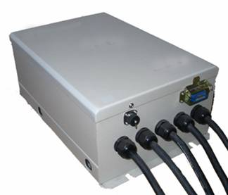
| Introduction | Controllers,U, V, W is the controller output terminal connected to the motor terminals of red, green, black. Forbid to connect reversed on terminal input P and output N to power source,or it will cause the break to the controller. | |
| Product Information: |
Controllers


The Relationship of PM BLDC Motor And Matching Controller Selection

Caution
1. U, V, W is the controller output terminal connected to the motor’s terminals of
red, green, black. Forbid to connect reversed on terminal input P and output N to power source,or it will cause the break to the controller.
2. The end of the motor is a encoder, do not unload and inspection on the motor
without professional support, or it will cause the break to the motor
3. This motor is water cooling type. If continuously working in accordance with
rated power and torque, radiating must not less than 5kw.If improve the radiating
can improve the performance class and the overload torque output time.
4. The material of the motor housing is aluminium, please keep away from acidity and alkali, unless it will.cause the rusty to the motor.This manual detail the performance, specifications mounting, usage and daily
maintain for DLC series, please keep in file. In order to correctly use the DL series motor,please read the instruction clearly.Introduction.This permanent magnet brushless DC motor system consist of the motor and controller, it is a typical mechanical andelectrical integration production. The stator winding of the motor is made into three-phase symmetric Y connection. The rotor of the motor is made of Nd, Fe, B magnet, Fe and B permanent magnetic material. The air-gap between the rotor and stator create the N-S alternative square wave magnetic field,in order to ensure the motor winding the actually convert direction,we build in a sensors on the motor, which to give the signalto the rotor. The features are as below:
1. High efficiency: there is not copper and iron waste on the rotator of the DC brushless motor.its efficiency is by 5%~12%higher than the same rating asynchnorous motor
2. High power factor: brushless DC motor need not to get magnetizing current from
electricity, power factor isapproximate 1.0
3. The brushless DC motor’s mechanical and regulation characteristic is similar
with separated excitation, with big starting torque and smallstarting current, wide regulation range and without the brush reversing trouble.
4. when at the same bulk and max operating speed, versus asynchnorous motor higher
30% EFF.
5. High adaptability: the deviation of speed within ±1﹪.
Main specification
Rated power:120 kW Peak power:200 kW(3min) Rated speed:3200 rpm Max speed:3600 rpm Rated torque:341.1 N·m Over load torque:1200 N·m (1min) Rated
Voltage:460VDCRated Current: 236A Working Mode:1h
Cooling:waterInsulation class:FIP44
Our company’s the controller model is in accordance with the following
definition,please check 3200r/min。For example:DLC120-3200,means water cooling permanent magnetic brushles DC motor,rated power is 120kw,rated speed is 3200r/min.

System diagram

The controller consist of IGBT power componentand Electronic circuit.
The input signal are start, stop, brake and encoder from motor, and outlet the
start, stop, brake, reverse, speed regulation signal and offer protect and state
display function.
Product installation


Before mounting the controller,ttend the follow matters.If any questions on the product,please contact us.The product which you purchase is accordance with the one you ordered?The product is broken during shipping. Our company’s the controller model is in accordance with the following definition,please check. P,N pole respectively connected to the power source positive poleand negative pole.U,V,W is the three phase terminated line,respectively connected to
the motor down-lead U(red),V(green),W(black).The wiring for motor’s position
sensor .The two end of connection line for the position sensor accompanying with the motor respectively connected to the motor and controller.The motor’s torque control The control mode of the permanent brushless DC motor is direct torque control ,according to formula T=Kt×I, Kt(torqueconstant)and Ke (back electromotive force coefficient) is equivalent in the values.they are all directly determined by themotor hardware,can not be changed.So,it is the
controller’s output current to determine the motor ‘s torque . The letter I refers to the motor’s phase current average value .The waveform of the current is as below
(Max phase current )(Average phase current)(Min phase current )
Operation explanation
To connect the sensor between the controller and the motor,and correctly connect the P,N pole between the power source and the controller,correctly connect the U,V,W end between the controller and the motor.To connect the accelerator and thecontroller, Turn on power after exam the connection,adjust the accelerator then you can achieve the motor speed adjustment P,N pole respectively connected to the power source positive pole and negative pole.U,V,W is the three phase terminated line,respectively connected to the motor down-lead U(red),V(green),W(black).The wiring for motor’s position sensor .The two end of connection line for the position sensor accompanying with the motor respectively connected to the motor and controller.The motor’s torque control The control mode of the permanent brushless DC motor is direct torque control ,according to formula T=Kt×I, Kt (torque constant) and Ke (back electromotive force coefficient)is equivalent in the values.they are all directly determined by the motor hardware,can not be changed.So,it is the controller’s output current to determinethe motor ‘s torque . The letter I refers to the motor’s phasecurrent average value .The waveform of the current is as below(Max phase current )(Average phase current)(Min phase current )Operation explanation To connect the sensor between the controller and the motor,andcorrectly connect the P,N pole between the power source and the controller,correctly connect the U,V,W end between the controller and the motor.To connect the accelerator and the controller, Turn on power afterexam the connection,adjust the accelerator then you can achieve the motor speed adjustment
Controller & contactor assembly Motor speed controller

Description
Curtis PMC Models BSC series brush DC motor controller are power MOSFET electronic
motor speed Controllers designed to provide smooth, silent, efficient and cost
effective speed, torque and braking control.
Application
Curtis PMC MOSFET motor speed Controllers are ideal for a variety of electric
vehicle applications, including indus-trial trucks, personnel carriers, material
handling vehicles and golf cars, etc.
Features
• High frequency switching and ultra low voltage drops provide very high efficiency
and silent operation. Costs, heatsinking requirements and motor and battery losses
are reduced. Low end torque, range and battery life are increased.
• Environmental protection provided by a rugged anodized aluminum extrusion housing. Simple mounting and wiring with push-on type connectors for control signals. Plated
solid copper busses used for all power connections.
• Thermal protection and compensation circuit provides constant current limit over
operating range and under temperature and over temperature cutback. No sudden loss
of power under any thermal conditions.
• No adjustments are required. Simple installation — Uses a two wire throttle potentiometer.
• Potentiometer fault protection circuitry disables controller if throttle wires
become open.
• High pedal disable prevents controller operation if key is turned on while throttle is applied.
• Plug braking diode internal to controller.
Specifications
• Frequency of Operation: 15 kHz
• Standby Current: less than 20 mA
• Standard Throttle Input: 0-5k ohms ±10% (others available)
• Weight: 1204/1204S: 1.8 kg (4 lbs); 1205: 2.7 kg (6 lbs)
• Full Power Operating Temperature Range: -25°C to 75°C (controller temperature)
Dimension


Diagram

Introduction

This permanent magnet brushless DC motor system consist of the motor and controller, it is a typical mechanical and electrical integration production. The stator winding of the motor is made into three-phase symmetric Y connection. The rotor of the motor is made of Nd, Fe, B magnet, Fe and B permanent magnetic material. The air-gap
between the rotor and stator create the N-S alternative square wave magnetic field,
in order to ensure the motor winding the actually convert direction, we build in a
sensors on the motor, which to give the signal to the rotor. The features are as
below:
1. High efficiency: there is not copper and iron waste on the rotator of the DC
brushless motor.its efficiency is by 5%~12% higher than the same rating asynchnorous motor
2. High power factor: brushless DC motor need not to get magnetizing current from
electricity, power factor is approximate 1.0
3. The brushless DC motor’s mechanical and regulation characteristic is similar
with separated excitation, with big starting torque and small starting current, wide regulation range and without the brush reversing trouble.
4. when at the same bulk and max operating speed, versus asynchnorous motor higher
30% EFF.
5. High adaptability: the deviation of speed within ±1﹪.
Main specification
Rated capacity:5~300 kVA Peak power:200 kW(3min) Rated speed:3200 rpm
Max speed:6000 rpm Over load torque:1200 N·m (1min) Rated Voltage:72~460VDC
Rated Current: 236A Working Mode:1h Cooling:air/water Insulation class:FIP54
Description

Curtis PMC Models BSC series brush DC motor controller are power MOSFET electronic
motor speed controllers designed to provide smooth, silent, efficient and cost
effective speed, torque and braking control.
Application
Curtis PMC MOSFET motor speed controllers are ideal for a variety of electric
vehicle applications, including indus-trial trucks, personnel carriers, material
handling vehicles and golf cars, etc.
Features
• High frequency switching and ultra low voltage drops provide very high efficiency
and silent operation. Costs, heatsinking requirements and motor and battery losses
are reduced. Low end torque, range and battery life are increased. • Environmental protection provided by a rugged anodized aluminum extrusion housing.
Simple mounting and wiring with push-on type connectors for control signals. Plated
solid copper busses used for all power connections. • Thermal protection and compensation circuit provides constant current limit over
operating range and under temperature and over temperature cutback. No sudden loss
of power under any thermal conditions.
• No adjustments are required.
• Simple installation — Uses a two wire throttle potentiometer.
• Potentiometer fault protection circuitry disables controller if throttle wires
become open.
• High pedal disable prevents controller operation if key is turned on while
throttle is applied.
• Plug braking diode internal to controller.
M&C ev-motor factory web:www.ev-motor.cn
GuangDong M&C Electric Power Co.,Ltd
Add:3/f Dizhi Building No.739 Dongfeng Rd.E Guangzhou China P.c:510080
Tel:+86-20-89660216 Fax:+86-20-89660219
http://www.china-electricmotor.com E-mail:mc@china-electricmotor.com
粤ICP备08124952号
