
The cooling of an electric motor is studied in this example. The motor consists of rotating and stationary parts. It heats up because of heat transfer from the engine to which it is mounted and because of frictional heating in the shaft bearings. Cooling is accomplished by coils mounted in the housing and to a lesser degree by the air gap between the rotating and stationary components
Results suggest that additional cooling is required for this particular motor and motor mount design.
The task of distributed power generation is generally achieved by a generator set consisting of an internal combustion (IC) engine coupled with an electric motor. Cooling the electric motors is a challenging task. In addition to the heat released from the coils, the motors receive additional heat flux from the attached IC engine. The air gap, which is confined between the rotor and stationary components (stator and housing), is generally very small and does not contribute significantly to the cooling process.
When this is the case, cooling water is circulated through the coils in the motor housing to dissipate the heat. This example simulates one such situation and predicts the heat load distribution on various components of the electric motor. The computational results provide detailed insight into the motor cooling process, and can be used to guide the design of alternate strategies for effectively cooling the motor.
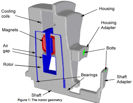
Using FLUENT, a 30 degree periodic sector of the motor is analyzed. The calculation domain (Figure 1) consists of the engine shaft, rotor, stator, magnets, motor housing, and shaft and housing adapters, which are used to bolt the motor to the engine. The stator, not shown in the figure, lies inside the rotor and housing, extending from the region below the magnets to the region inside the outer portion of the motor housing. It has a cross-section with the shape of the letter "I". With the exception of the stator, all solid motor components are simulated as conducting walls (solid zones), throughout which the energy equation is solved.
The rotor is separated from the motor housing and stator by an air gap (blue). It contains a pair of magnets (red) that rotates with the rotor. The motor is bolted to the engine using housing and shaft adapters. The bolts used to make the connections, with cross-sections shown in green, transfer a significant amount of heat from the engine to the motor. Gaskets between the adapters and engine mounts are used to minimize this heat transfer.
Convection heat transfer boundary conditions are applied on the exterior surfaces of the housing. Cooling coils, mounted in the engine housing, are also modeled using this boundary condition. Temperatures are specified on the adapter surfaces. The faces of the adapter surfaces that are covered with gaskets are modeled using the thin wall thermal resistance boundary condition. This special boundary condition allows for a thin layer of conducting material (the gasket) between the external boundary (the engine) and the fluid or conducting wall zones (the adapters) on the interior of the domain. The circular bolt-connecting surfaces are described by constant temperature boundary conditions. The stator surfaces are treated as external boundaries with a varying temperature in the radial direction.
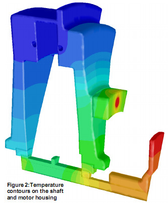
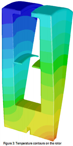
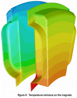
Figure 2 shows contours of temperature on the shaft and motor housing. The temperature contours illustrate the heat influx to these components from the engine. Contours of temperature on the rotor are shown in Figure 3. Higher temperature can be seen at the lower right corner (and to a lesser extent, the lower left corner) of the rotor. This is mostly due to heating from the shaft adapter, and partly due to the heat source that is included to represent frictional heating at the site of the shaft bearings. Temperature contours on the magnets are shown in Figure 4. They illustrate that the regions closest to the engine (lower right) receive inadequate cooling compared to those elsewhere.
In summary, a CFD analysis of an electric motor mounted onto an IC engine has shown that water coils are effective in cooling only part of the motor section - that which
is more distant from the engine. Regions of the motor components closest to the engine (magnets, rotor, and housing) showed consistently higher temperatures due to direct heat influx through the adapters and frictional heating in the bearings. The computational results showed that additional cooling or heat protection would be necessary in the housing adapters to avoid damage to the magnets on the engine side. In addition, higher coolant flow through the engine side tube would yield better cooling on the engine side of the motor.
Courtesy of Lynx Motion Technology, Inc. (www.lynxmotiontechnology.com)
Guangzhou Haoqing Mechanical and Electrical Equipment Co.,Ltd GuangDong M&C Electric Power Co.,Ltd
Add:Room 104, No. 8 JinXian Street, YiJing Road, Haizhu District, Guangzhou, China P.c:510080
Tel:+86-20-89660216 Fax:+86-20-89660219
http://www.china-electricmotor.com E-mail:mc@china-electricmotor.com
粤ICP备08124952号
